machining surface finish symbols triangle
1142 Machine Pattern and Forging Dimensions. The indication of surface roughness values in the surface finish symbols are shown the figure A.
2
Geometric Dimensioning and Tolerancing GDT is a system for defining and communicating engineering tolerances and relationships.
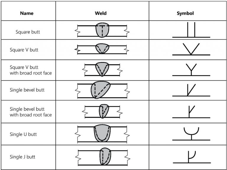
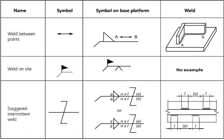
. The table presents some of the most commonly used welding symbols. You can think of them as anchors for the entire part. 47 Drawing a Right Triangle With Hypotenuse and One Side Given.
If the value has a line underneath it the finish should be done by a. Enter the email address you signed up with and well email you a reset link. 1141 Dimensioning for Numerically-Controlled Machining.
Fillet The most used weld. 1010 Dimensional Accuracy and Surface Finish. It uses a symbolic language on engineering drawings and computer-generated three-dimensional solid models that explicitly describe nominal geometry and its allowable variation.
Surface texture obtained by the removal of material by machining operations like. Enter the email address you signed up with and well email you a reset link. 1012 Computer-Integrated Manufacturing.
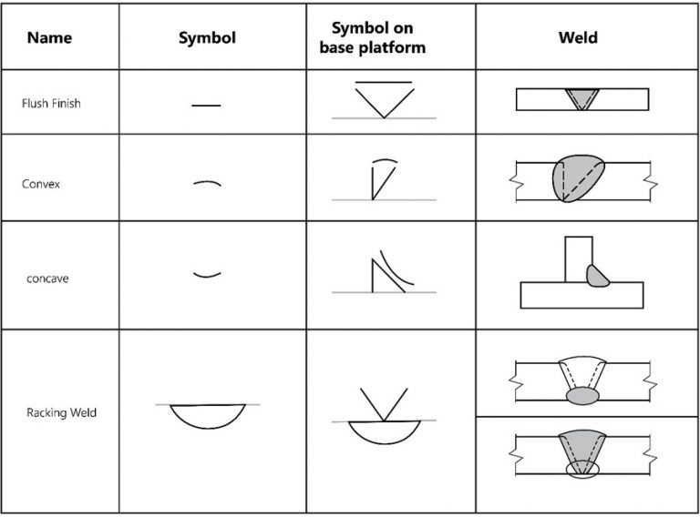
Engineers use this symbol to indicate both the surface finish and the technique that should be used to produce that finish. It usually involves preparing the edge pieces to form one of the groove weld shapes like V bevel U J Flare V Flare bevel or no preparation at all with square edges to form a square groove. A If the surface roughness is obtained by any production method other than machining the value of surface rough necessary.
A datum feature is the tangible surface or feature of size comprised of multiple surfaces or revolved surfaces that is indicated by the datum feature symbol. Position is one of the most useful and most complex of all the symbols in GDTThe two methods of using Position discussed on this page will be RFS or Regardless of Feature Size and under a material condition Maximum Material Condition or Least Material ConditionHowever since this is such a useful symbol we will continue to add content and examples for other uses of this. The number in the checkmark corresponds to the roughness value.
This symbol has a bar added to the basic symbol and forms a triangle. 46 Drawing a Triangle With Sides Given. Groove Second most used.
Datums are theoretically exact points axes lines and planes or a combination thereof that are derived from datum features. It indicates a surface that requires a material removal process and allowance indicated. It tells the manufacturing staff and machines what.
The finish on a metal surface after machining depends mainly on the material and some are as follows.
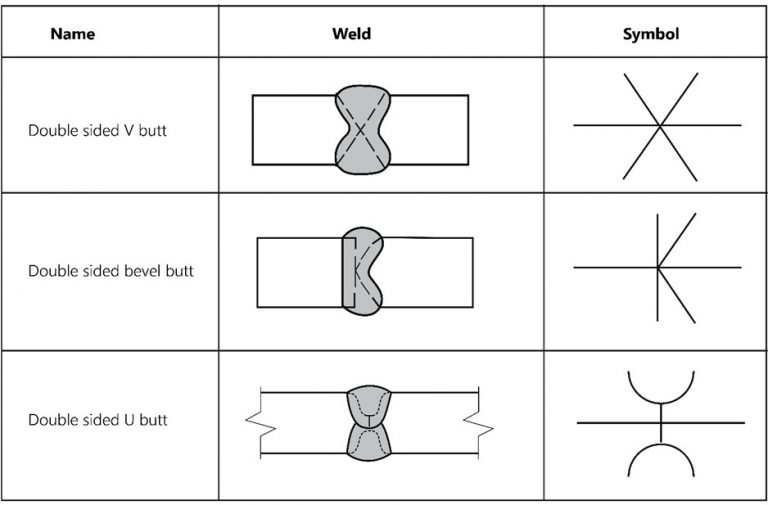
Understanding The Welding Symbols Explained With Diagrams Cruxweld
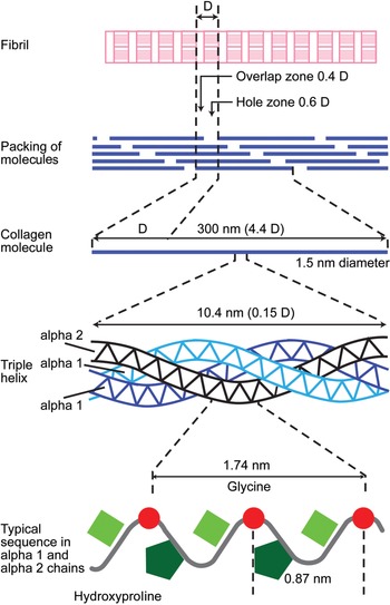
Applied Basic Sciences Section 5 Postgraduate Orthopaedics
Understanding The Welding Symbols Explained With Diagrams Cruxweld

Understanding The Welding Symbols Explained With Diagrams Cruxweld
Latest Mechanical Engineering General Discussion Topics Simpliengineering
Understanding The Welding Symbols Explained With Diagrams Cruxweld
Fatigue Springerlink
Understanding The Welding Symbols Explained With Diagrams Cruxweld

Surfaces Free Full Text Design Of Deterministic Microstructures As Substrate Pre Treatment For Cvd Diamond Coating Html

Understanding The Welding Symbols Explained With Diagrams Cruxweld

Flange Face Finish

Understanding The Welding Symbols Explained With Diagrams Cruxweld
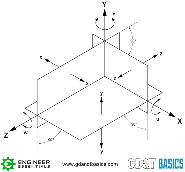
The Asme Y14 5 Gd T Standard Gd T Basics
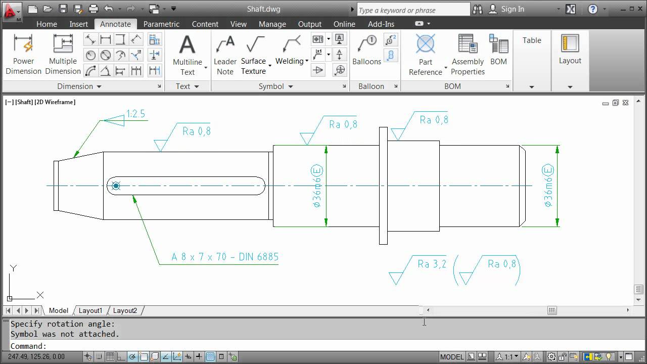
Annotating With Symbols Autocad Mechanical 2012 Youtube

The Asme Y14 5 Gd T Standard Gd T Basics
![]()
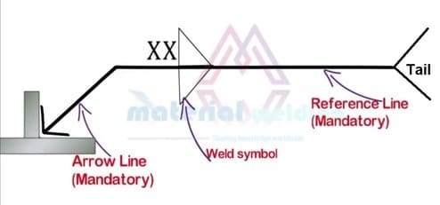
Welding Symbols Www Materialwelding Com

Developing Safe Lathing Parameters For Pbx 9501 Woodrum 2018 Propellants Explosives Pyrotechnics Wiley Online Library
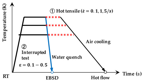
Metals Free Full Text A Physical Based Plane Stress Constitutive Model For High Strength Aa7075 Under Hot Forming Conditions Html
Welding Symbols Www Materialwelding Com